DYNA-TITE APPLICATION
Dyna-tite cable locks and wire rope can be used for suspension in a variety of ways to accommodate most mechanical & HVAC construction applications.
Standard Assembly
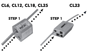
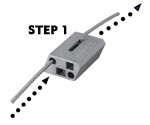
STEP 1
Pull the release pin back and thread the wire rope into one locking channel in the cable lock. Failure to pull adjustment pin first may cause damage to serrated teeth and reduce holding capacity.
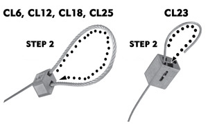
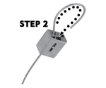
STEP 2
Pass the wire rope “tail” through (or around) the anchor point (Eyehook, Beam, or Purlin).
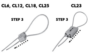
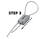
STEP 3
Pull the release pin back and push the wire rope tail into the second locking channel in the cable lock. Push through at least 6″ of wire rope.
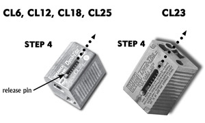
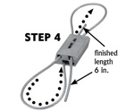
STEP 4
Prior to the load being applied, the wire rope can be adjusted in either direction by sliding the release pin and moving the wire.
ALWAYS CONFIRM ENGAGEMENT OF CABLE LOCK ON WIRE BEFORE APPLYING THE LOAD BY PUSHING THE ADJUSTMENT PIN IN THE OPPOSITE DIRECTION OF THE ARROWS ON THE CABLE LOCK AND THEN PULLING THE CABLE, ALSO IN THE OPPOSITE DIRECTION OF THE ARROWS ON THE CABLE LOCK.
Adjusting The Cable Lock
With the load off the wire rope and the Cable Lock, push the release pin in the direction of the arrow on the Cable Lock. This will release the locking pawl and allow the wire rope to be moved freely in either direction. (After a load has been applied it may be necessary to pull the cable slightly to disengage the teeth on the pawl). Be sure the load is fully supported before attempting an adjustment.
*Please note, the CL23 has 2 pass through holes. Use only the locking channels for standard assembly.
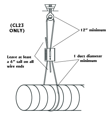
Optional Figure 8 Assembly (CL-23 ONLY)
STEP 1
Thread the wire rope into the “through hole” in the CL23.
STEP 2
Pass the wire rope “tail” through (or around) the anchor point (Eyehook, Beam, or Purlin).
STEP 3
Pull the release pin back and push the wire rope tail into one locking channel in the CL23 and pull at least 6 in. of the wire rope through. Failure to pull adjustment pin first may cause damage to serrated teeth and reduce holding capacity.
STEP 4
Pass the other wire rope end through (or around) the bracket or fixture on the object to be suspended. return the wire rope to the CL23. Pull the release pin back and push at least six inches of wire rope through the remaining locking channel. For final adjustment see step 4 above in standard Assembly.
ALWAYS CONFIRM ENGAGEMENT OF CABLE LOCK ON WIRE BEFORE APPLYING THE LOAD BY PUSHING THE ADJUSTMENT PIN IN THE OPPOSITE DIRECTION OF THE ARROWS ON THE CABLE LOCK AND THEN PULLING THE CABLE, ALSO IN THE OPPOSITE DIRECTION OF THE ARROWS ON THE CABLE LOCK.
APPLICATIONS:
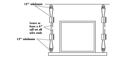
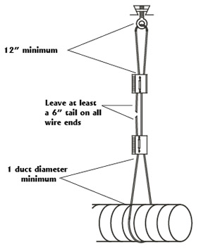
Leave at least a 6″ tail on all wire ends
Unit Hanging
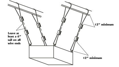
Rectangular Ductwork
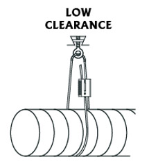
Spiral Ductwork – Low Clearance
Spiral Ductwork – Two Cable Locks
Spiral Ductwork – Figure 8 (CL23 ONLY)